The 40 meter band (7.000-7.200 MHz) is the workhorse of amateur radio. By day it reaches across a region, by night it crosses oceans. And the antenna that works best for it is also the cheapest antenna you can build: a half-wave dipole made from wire, rope, and a piece of PVC pipe.
This guide shows the exact math, a shopping list you can fill at any hardware or electronics shop, how high to hang it, which coax to buy, how much power the materials can take, and which radios to pair it with. It is still the antenna experienced hams recommend to almost every new operator.
What you are building
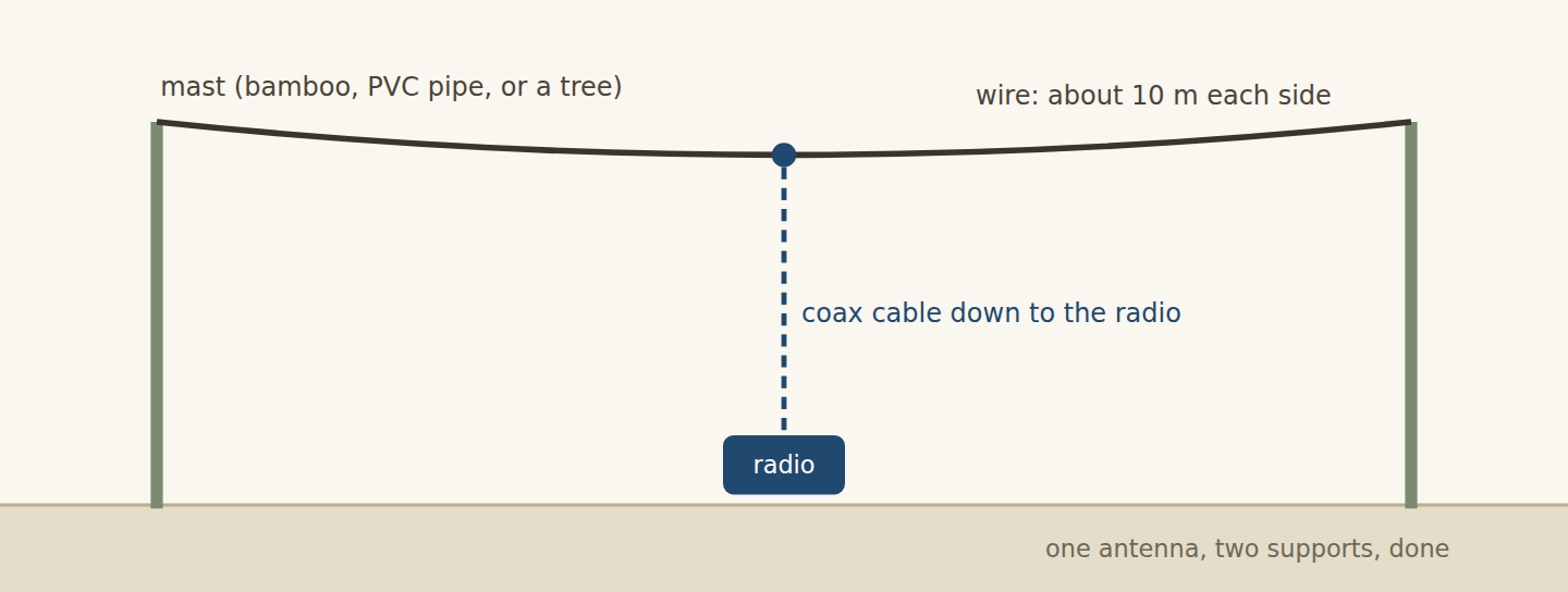
A dipole is a straight wire cut in half. Your coax cable connects in the middle: the center copper goes to one half, the braided shield goes to the other. Radio energy flows out of the coax, onto both wires, and into the sky. That is the entire concept. Everything else is detail.
The math: how long should the wire be?
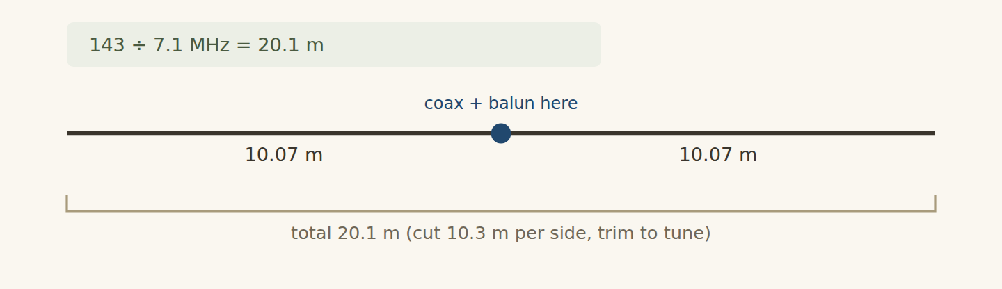
An antenna resonates when each half is a quarter of the wavelength. For a wire dipole, the practical total length in meters is:
You want the whole band from 7.000 to 7.200 MHz, so aim for the middle: 7.100 MHz.
Cut each side a bit long, about 10.3 m, because you will trim the ends later while checking SWR (more on that below). If you work in feet, the same rule is 468 ÷ frequency in MHz, which gives about 65.9 feet total here.
Shopping list
Nothing here is exotic. In most towns you can buy all of it in one trip:
| Item | Spec | Notes |
|---|---|---|
| Flexible copper wire | 2.5 mm² (about AWG 14), 21 m | Electrical "flex" or THHN wire. Stranded is easier to roll up. |
| Coax cable | RG-6 or RG-58, 15-20 m | RG-6 (TV/satellite type) is the budget pick. See the coax section. |
| PVC pipe | 15-20 mm, 30 cm piece | Becomes the center insulator. |
| PVC pipe, larger | 50-75 mm, 1 m piece | Becomes the choke balun former. |
| Nylon rope | 4-6 mm, 20 m | To hang the ends. Avoid plain sisal; it rots. |
| End insulators | 2 pcs | Dog-bone ceramic is nice; a piece of stiff bottle plastic drilled twice works for years. |
| Small hardware | hose clamps, cable ties, screws | To keep the wire from sliding on the PVC. |
Building it, step by step
1. Cut two wires of 10.3 m each. Mark the extra 25 cm at every end with tape, because that part is your trimming reserve.
2. Drill two small holes through the PVC pipe. Pass one wire through each hole and secure it with a hose clamp or a few tight wraps plus cable ties. The two wires must not touch each other.
3. Solder the coax: center copper to the left wire, braided shield to the right wire. Seal the joint with self-amalgamating tape or a dose of hot glue inside the pipe so rain cannot reach it.
4. Add the choke balun just below the center, then hoist the antenna.
5. Tie the end insulators to the rope and pull the wires out horizontally, or slightly in a shallow V if you lack the full 20 m span. Even a V shape works surprisingly well.
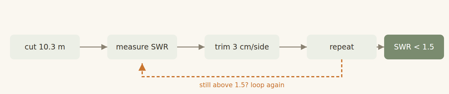
6. Connect the coax to the radio, check SWR, and trim both wire ends by 2-3 cm at a time until the reading drops.
About the balun (short version)
The center of the antenna carries a choke balun: a few turns of the coax cable wound around a piece of PVC. Its job is simple to say and easy to skip, so do not skip it. It stops radio energy from crawling down the outside of your coax, which otherwise turns the cable into an extra antenna and your shack into part of the radiation pattern.
For this build, 8-10 turns of the coax on a 50-75 mm former, placed right below the center insulator, is enough to get you on the air.
How high should it hang?
Height is the one variable you cannot fix with money later, so push for as much as your supports allow.
| Height | What you get |
|---|---|
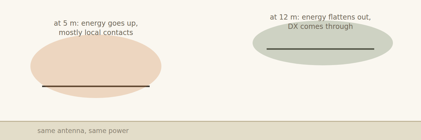
| 5-6 m | Works, but the signal leaves the antenna steeply. Good for regional contacts a few hundred km, weak for DX. |
| 7-10 m | The sweet spot for most backyards. Balanced local and DX performance. |
| 12 m and up | The signal flattens toward the horizon. This is where DX happens. |
Keep the wire at least a meter away from metal roofs, gutters, and solar panels. Metal nearby absorbs the signal and detunes the antenna.
Which coax to buy
Coax is where beginners overspend or underspend, rarely correctly. On 7 MHz (40 m) the losses are gentle, so the honest answer is:
RG-6 (the white or black cable used for satellite TV) is the budget pick, and it is genuinely good here. It is 75 ohm instead of 50, which sounds like a problem, but a dipole hung at a practical height already has a feedpoint impedance somewhere between 50 and 75 ohm, so the mismatch stays small and any internal tuner handles it easily. It is cheap, thick, low-loss, and available in every electronics shop. For runs under 25 m it is a very sensible default.
RG-58 is the classic thin ham coax. Perfectly fine up to about 15 m at 100 W. Beyond that its losses and power handling start to matter.
RG-213 is the fat one for long runs or high power. Buy it when you actually need it, not before.
Whatever you choose, keep the run short. A 40 m antenna in the yard with a 10 m cable beats the same antenna behind the house with 30 m of cable.
How much power can this take?
The wire itself is not the limit. A 2.5 mm² copper wire at 100 W barely warms; even at 500 W it does not care. The practical limits are elsewhere:
- Your license class. Most entry licenses set the maximum transmit power, often 100-500 W. Whatever your ticket says, that is your number, and it outranks everything below.
- The coax. RG-58 is comfortable around 100 W on this band. RG-6 and RG-213 handle several hundred watts without drama.
- The connectors. A badly soldered PL-259 fails before any cable does.
For learning, 50-100 W is plenty on 40 m, and 5-10 W from a QRP radio also makes contacts when the band is kind. Start low, work up.
Radios that pair well with this antenna
Any HF transceiver that covers 7.0-7.2 MHz will be happy with a resonant dipole. A few that new operators commonly buy:
| Radio | Power | Why it fits this build |
|---|---|---|
| uSDX / QCX (kit) | 5-10 W | Cheapest entry. A dipole at 7 MHz is the natural partner for a QRP radio. |
| Xiegu G90 | 20 W | Popular starter rig, built-in tuner and SWR display, survives abuse. |
| Yaesu FT-450D (used) | 100 W | The second-hand workhorse. Often the best value on the used market. |
| Yaesu FT-891 | 100 W | Compact full-power mobile rig, good if you also operate portable. |
| Icom IC-7300 | 100 W | The modern standard. Costs more, keeps its value, screen shows you the whole band. |
If your radio has an internal tuner, still tune the antenna by trimming first. The tuner then only cleans up the last few percent, instead of hiding a badly built antenna.
Tuning it: SWR without tears
SWR (standing wave ratio) is a number from 1 to infinity that tells you how well the antenna accepts your power. 1 is perfect, anything under 1.5 is great, under 2 is fine, over 3 means most radios will throttle themselves to protect their transistors.
The routine: measure SWR at 7.060 MHz and at 7.150 MHz. If the reading is lower on 7.060, the antenna is too long, trim 3 cm from each end. If lower on 7.150, it is too short, and you should have kept your trimming reserve. Repeat until both ends read under about 1.5.
Mistakes everyone makes once
Forgetting that both halves must be the same length. A dipole with 9 m on one side and 11 m on the other tunes like nothing you have ever seen. Measure both, twice.
Skipping the choke balun and then wondering why the SWR changes when you touch the coax. That is the cable radiating, and the choke is the fix.
Hanging the wire along a metal fence or under a tile roof "because it was convenient". Height and distance from metal are the two things worth fighting for.
Trimming the wire to exactly 10.07 m and calling it done. The formula gets you close. Your roof, your soil, and your wire insulation shift it, which is why you cut long and trim to the SWR meter.
Quick answers
Can I run the wire in an inverted V instead of flat? Yes. A V with about 90-120 degrees between the halves performs close to a flat-top and needs only one tall support.
Is 20 m of space really needed? A shallow V shortens the span requirement. Bending the last 2 m of each end downward also works with minor loss.
Do I need an antenna tuner? Not if the antenna is trimmed right. A tuner is insurance, not a substitute for building it correctly.
Written for baron.id · comments and corrections from fellow hams are welcome · 73