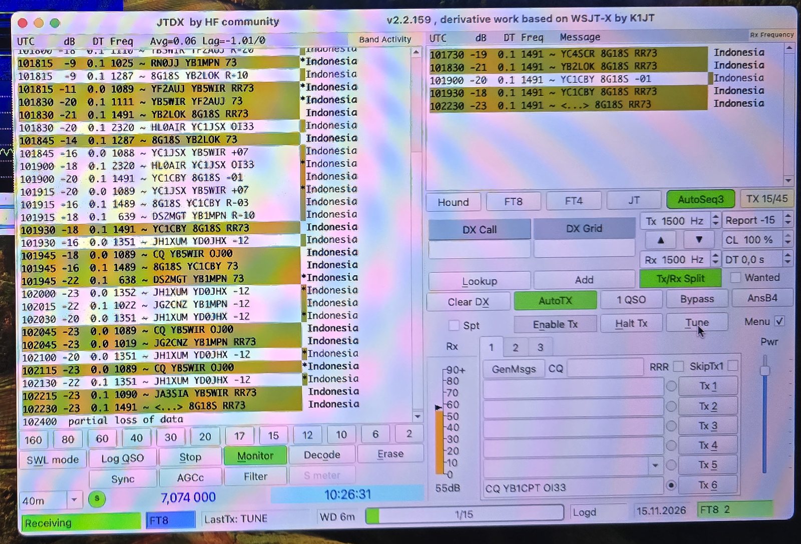
In the FT8 on a Hackintosh article, one problem was left open. The receive audio from the Yaesu FT-857D into the Digirig was far too hot. The JTDX input meter sat at 88–90 dB even with the macOS input slider almost at zero. The fix is a small hardware mod: one cut across a solder jumper marked ATT on the Digirig's circuit board. It took one craft knife, a cheap multimeter and a few minutes. The meter dropped from about 90 dB to 55 dB. Here is how it went, including the mistake I made with the multimeter.
Why the receive level was too hot
The FT-857D's DATA socket gives a fixed receive audio level, and there is no menu to turn it down. The Digirig's USB sound chip, on the other hand, does not attenuate much in software. Together they overload the input: the slider in Audio MIDI Setup barely changes the JTDX meter. Very strong stations then clip the audio and can hide weaker signals right next to them.
The Digirig designer anticipated this. On the back of the board there is a solder jumper marked ATT. From the factory its two halves are joined by a thin copper bridge. Cut the bridge and a resistor divider comes into the receive path, roughly −20 dB. Bridge it again with solder and you are back to stock.
What I used
- Digirig Mobile, Rev 1.9 (printed on the board)
- A sharp craft knife (cutter)
- A basic DT-9205A digital multimeter
- Good light, and fresh eyes. I postponed the cut by one night because my eyes were tired, and I recommend the same.
1 · Find the right pad
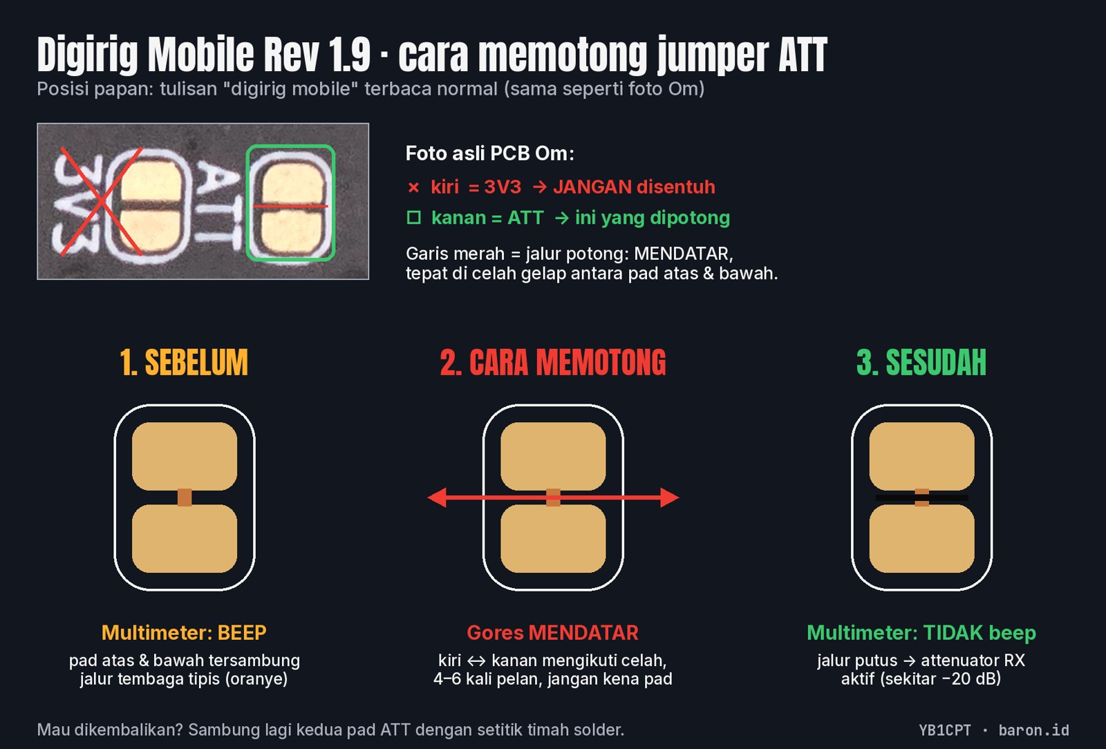
On the back of the Digirig Mobile Rev 1.9, next to the 3.5 mm jacks, there are two small pad pairs side by side: 3V3 and ATT. Only ATT gets cut. Leave 3V3 alone; it is a power jumper.
Each pad is split into two halves. The copper bridge runs across the narrow gap between them. So the cut goes along the gap, not across the halves. To make that clear before picking up the knife, I prepared a small guide:
2 · Make the cut
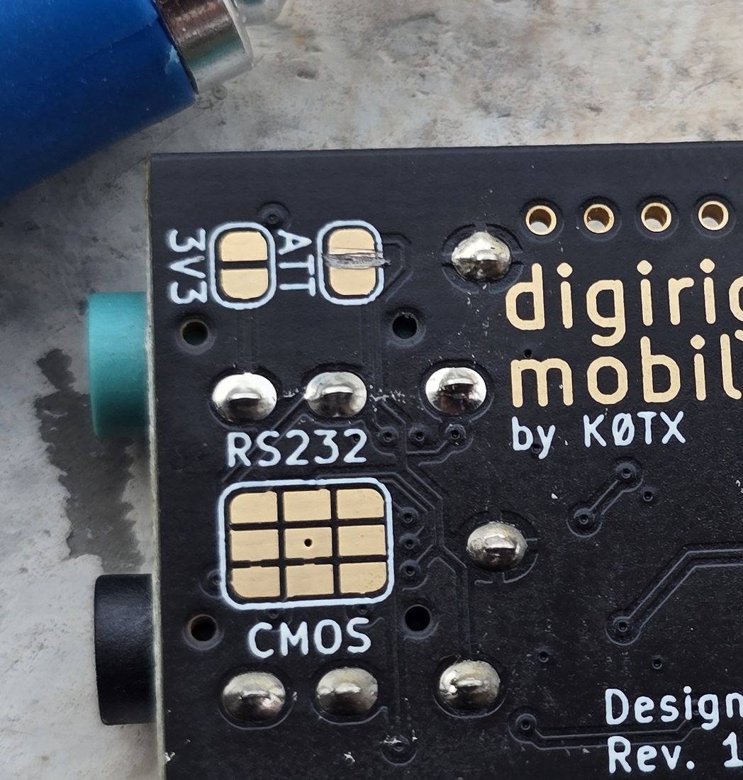
Hold the knife tip in the gap and score lightly along it, four to six strokes, rather than one hard push. The aim is to cut the thin copper bridge, not to dig into the board. When the bridge is through, you see a thin bright line of bare copper in the gap. Brush away the copper dust afterwards so no sliver can reconnect the halves.
3 · Check it with a multimeter (and my mistake)
You cannot judge a cut this small by eye. A multimeter tells you for sure. My first attempt was wrong: the dial was on DC volts. In that mode the meter only measures voltage, so it would never beep or show a short.
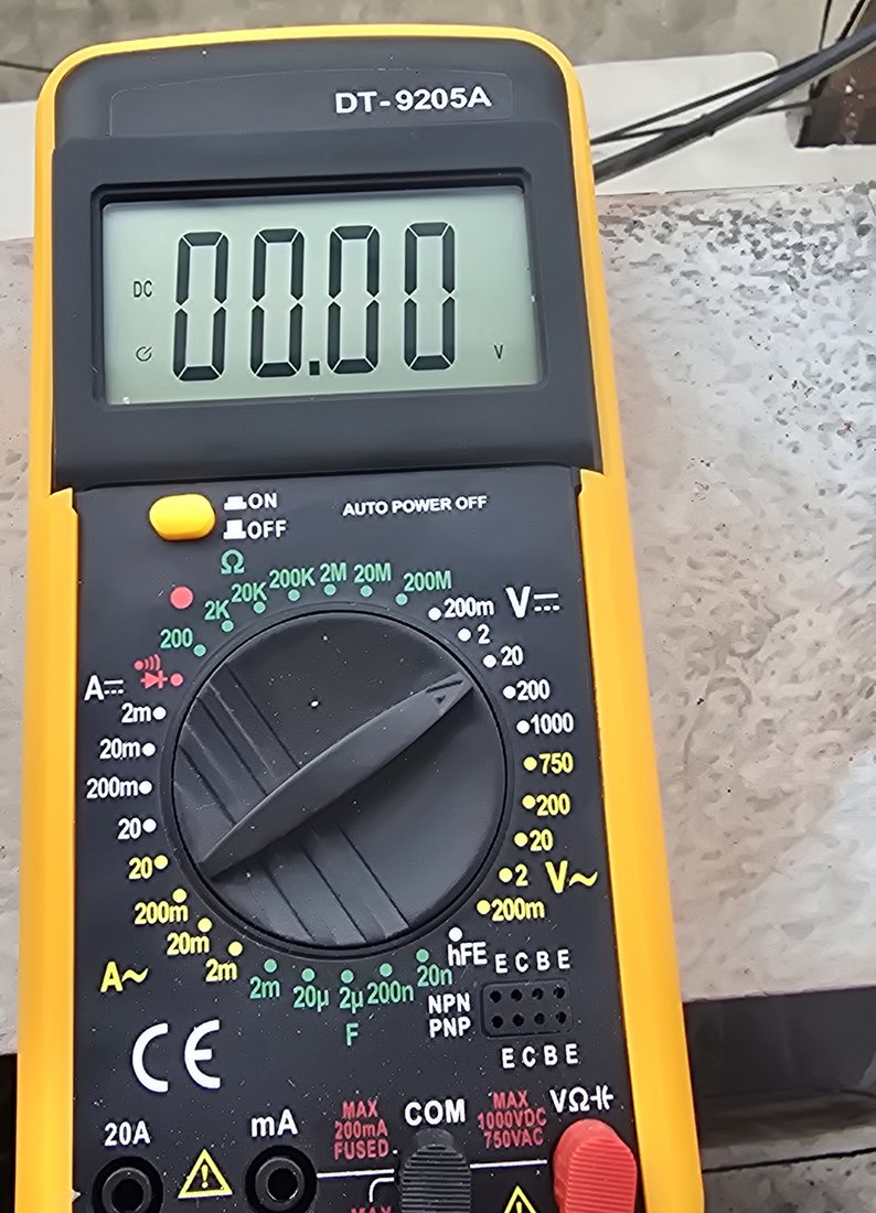
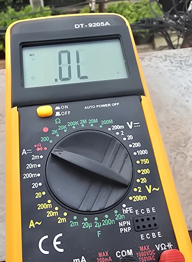
On the DT-9205A, the right position is the red diode / buzzer symbol, or the lowest resistance range, Ω 200. With the probes apart, the display shows .0L (open, over limit).
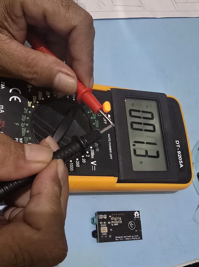
Before you trust any reading, touch the probe tips firmly together. My first try only crossed the probe shafts and showed a meaningless 1.8. Tip to tip, it read 1.3 Ω, which is just the resistance of the test leads. Now the meter itself is proven.
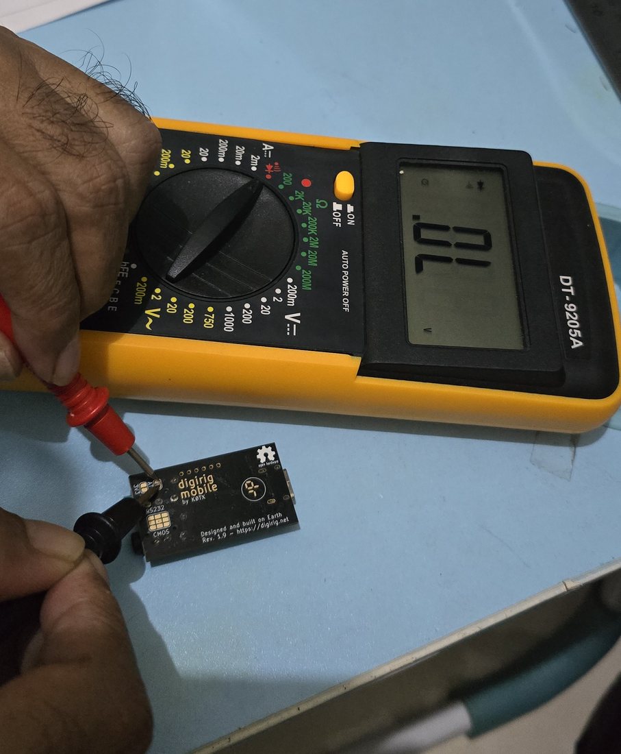
Then put one probe on each half of the ATT pad. It reads .0L: open, the bridge is cut. As a control, the same test on the intact 3V3 pad should read close to 0 Ω and beep.
4 · The result in JTDX
Back on the Hackintosh with the FT-857D on 7.074 MHz, the JTDX input meter now sits at about 55 dB instead of the 88–90 dB of the night before. The band was busy with JA, HL, DS and YB stations, and the decodes kept coming. More important, the Audio MIDI Setup input slider now really controls the level, so the last few dB down to the 30–50 dB sweet spot are a simple slider move.
| Before | After | |
|---|---|---|
| JTDX input meter (40 m) | 88–90 dB, stuck | about 55 dB |
| macOS input slider | almost no effect, even at 0.04 | works normally |
| ATT pad (multimeter) | bridged | .0L, open |
| Cost | nothing but a few careful minutes | |
Tips
- Check your board revision first. Pad names and positions can differ between Digirig versions. Read the silkscreen on your own board.
- Several light strokes, not one hard one. The bridge is very thin, and a slip could damage nearby traces.
- Test the meter before testing the board. Wrong dial position and probes that are not really touching both give misleading readings.
- Reversible. A small blob of solder across the two ATT halves undoes the mod.
- Still seeing "partial loss of data"? That is an audio dropout, not a level problem. Try a rear USB port directly on the motherboard rather than a hub.
Coming next
- Automatic QRZ uploads on the Mac: JTDX → RUMlogNG → QSO Upload Utility, so each QSO reaches QRZ.com when I press OK
- TX power and ALC on the FT-857D for clean FT8 transmit
Written for baron.id · 73 de YB1CPT